i got your gaswind right here
Attachments in this post:
http://fx-td.com/houdiniandchill/wp-content/uploads/discord/20263803/12/26/fart.gif
i got your gaswind right here
Attachments in this post:
http://fx-td.com/houdiniandchill/wp-content/uploads/discord/20263803/12/26/fart.gif
so this is pretty much the setup. It will animate and move along with the char, and instance geo onto it
Attachments in this post:
http://fx-td.com/houdiniandchill/wp-content/uploads/discord/20264402/26/26/image.png
http://fx-td.com/houdiniandchill/wp-content/uploads/discord/20264402/26/26/simple_growth_curves_pyro_spread2.hiplc
Yep. Will send when back on comp. It is ugly so have high expectations for carnage.
Random “emitter” . Constraints need to be not so shit. But here is the carnage.
Attachments in this post:
http://fx-td.com/houdiniandchill/wp-content/uploads/discord/20261802/19/26/laptops.hipnc
http://fx-td.com/houdiniandchill/wp-content/uploads/discord/20261802/19/26/laptops.gif
Can easily replicate a single source emitter.
“`cpp int trigger = int(rint(rand(@piece_id)*215));
if(@Frame<trigger){ @P = v@P_orig; @P.x = (noise(@Time*.4)-0.5)*8; // or just tracking an object pos v@v = {0, 1, 0}; }
if(@Frame>trigger){ @pscale += 15; @pscale = clamp(@pscale, 1, 100); } “`
Attachments in this post:
http://fx-td.com/houdiniandchill/wp-content/uploads/discord/20261602/19/26/single_source.gif
yeah
so normally I will set my density to the highest fidelity I need, and unless there is some insanely detailed velocity requirement will up the Vel scale
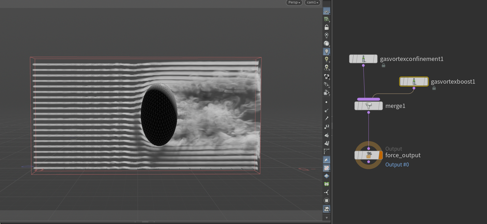
@hanhanxue VDB point advect will still suffer from not being able to 100% push them into the smaller eddies, so I think it’s best to just own it all in the pyro sim. I took Matt’s file and just added these vortex nodes. It’s a bit heavy handed here, but vortex confinement and vortex boost along with nice substeps will give you control to make these swirls. You can click the initialize option on the SOP pyro to drop down a volumes sharpen setup. This will sharpen density _just_ a bit more, saving you some precious sim time.
Attachments in this post:
http://fx-td.com/houdiniandchill/wp-content/uploads/discord/20253911/09/25/image.png
http://fx-td.com/houdiniandchill/wp-content/uploads/discord/20253911/09/25/porno_for_pyro.hip
shit i have done to help fill in gaps between points like that: – copy the points a few times and offset each copy a different random amount along v if a pop sim, or if it’s procedural distortion keep N up to date through the distortion and move them at right angles to it to avoid making the shapes fluffier – transform to NDC, flatten in Z and calculate density by finding average distance of closest 10 points or whatever so you have a screen-space measure of how “piled up” the points are getting and can avoid adding too many in dense areas – render velocity or screen space tangent vector AOVs, dilate or infill them in comp, then vector motion blur which will follow the shapes and avoid blurring across them – vector blur in comp just based on image gradient – should be easy in cops now to do slope blur which blurs along contours instead of across, usually makes things look “silky”… it’s what you do for hair retouching in shampoo ads
it’s stupid
can we see your rasterize volume?
before it goes into axiom
Attachments in this post:
http://fx-td.com/houdiniandchill/wp-content/uploads/discord/20252210/15/25/image.png
it can be sped up
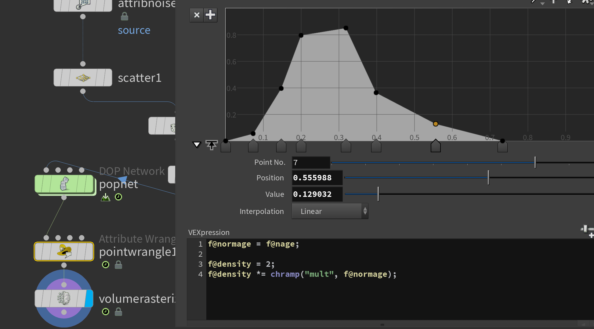
regarding creating density, here’s a little trick I use with all my sourcing. It makes the emission more natural, and reduces having bad looking sourcing visible.
mult your density with a remapped normalized age. This starts it out from zero, ramps up, and fades down
Attachments in this post:
http://fx-td.com/houdiniandchill/wp-content/uploads/discord/20254410/15/25/image.png
another option, that I use for a lot of custom shaping
Attachments in this post:
http://fx-td.com/houdiniandchill/wp-content/uploads/discord/20250408/30/25/spread_byvel.mp4
http://fx-td.com/houdiniandchill/wp-content/uploads/discord/20250408/30/25/spread_byvel.hiplc