Archived post by solitude9206

Yeah pretty much.

I’ll try some sneaky stuff tomorrow with symlinks

Ok so far the easiest thing I found was the assign material node – adding a parameters override – it basically clones the material for you and just sets the attr and assigns the copy of the material to the geo. You can have it reference primvars from the geometry as well, so I can do s@inputs:file = s@txpath; But it can’t do **_geo and loop ove the prims, so I still have to do it in a for each (which I haven’t done yet.

But… this in itself ‘kinda’ makes the point inmho that you can definitely clearly define a primvar/attr AS a texture up front, and collect them ahead of time for the renderers

I take it back. It works with ** so yay.

Easy enough for me

Archived post by pixel_bender

…and final thing… in import to SOPs, the @name attribute created will always be the mesh component of the path attribute? @path = ‘/path/to/mesh’ @name = ‘mesh’

For anyone interested.. Ive just RFEd for some documentation improvements for the RBD procedural workflow, but also this is my summary
“`Incoming LOP geometry in SOPs will contain @name and @path attributes. @path will be the USD prim path and should be maintained for the round trip to SOPs and back to LOPs. “/root/myGeometry/mesh01” @name will be equivalent to the mesh component of the full @path (and aids in the construction of USD hierarchies in the absence of @path) “mesh01”
Outgoing geometry Input geometry transformation will now be driven by the RBD simulation’s point transforms. As such we need to establish a relationship between the RBD simulationn points and the newly fractured geometry pieces, while creating no additional pieces in the USD hierarchy. While the fracture creates many pieces of geometry, if those pieces carry the same @path attribute, they will have a singular mesh path in USD, maintaining the original input path hierarchy upon return to LOPs.
FOR THE STATIC FRACTURED GEOMETRY We establish this relationship with a primitive @piecename attribute – which would be the concatenated string of the incoming mesh (ie @name) + the piece naming as derived from your fracturing process. @piecename = “mesh01-piece0-1” (while maintaining @path = “/root/myGeometry/mesh01”) @piecename = “mesh01-piece0-2” (while maintaining @path = “/root/myGeometry/mesh01”) … FOR THE SIMULATION POINTS We establish this relationship with a point @piecename attribute that differs from the fractured geometry in that it will be the concatenated string of the full path (ie @path) + the piece naming as derived from your fracturing process.   @piecename = “/root/myGeometry/mesh01-piece0-1” @piecename = “/root/myGeometry/mesh01-piece0-1″“`

I feel if the docs kinda spelt this out a little more for the dummies in the back like me, they might make a little more sense than just a rote learning excercise in dropping nodes

I feel like the above falls under ‘assumed knowledge’ – but it’s only assumed by USD eggheads, not your average SOPsy artist looking to bring their workflows to LOPs

This is my take on: www.sidefx.com/docs/houdini/solaris/houdini_rbd_procedural.html

Archived post by pixel_bender

In case anyone’s interested, I actually collate a lot of my learning and discover into these kind of master files.

The green nodes have content – the yellow are placeholders

There are text-based step throughs and descriptions for doing different stuff

I share these with my colleagues and add more zoic pertinent info – but they are files I develop in my time

And for me, its an invaluable resource when I cant remember just how to constrain something.. do projections.. or set up a scatter/instance workflow

actually sorry need to edit the file – left some junk in there

ok there we go @chris_gardner and @davebr

Attachments in this post:
http://fx-td.com/houdiniandchill/wp-content/uploads/discord/20245309/11/24/image.png

Archived post by waffleboytom

this works but I feel like it’s a hack

“`py node = hou.pwd() stage = node.editableStage()
prim = stage.GetPrimAtPath(‘/geo/points_0’)
ptsattrib = prim.GetAttribute(‘points’)
ptsarray = prim.GetAttribute(‘points’).Get()
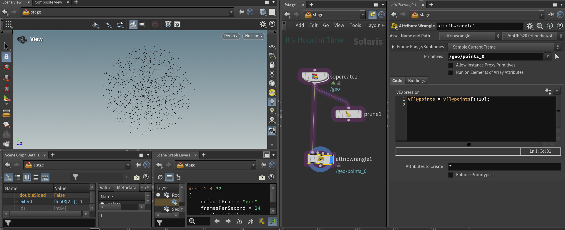
ptsattrib.Set(ptsarray[::10]) “` weirdly enough the python version doesn’t seem to affect the HoudiniDataId while the vex version sets it to -1 which makes me go hmmmmm

“`py node = hou.pwd() stage = node.editableStage()
prim = stage.GetPrimAtPath(‘/geo/points_0’)
attribs = prim.GetAttributes()
for attrib in attribs:
interp = attrib.GetMetadata(“interpolation”)
if interp == “vertex”:
valarray = attrib.Get() attrib.Set(valarray[::10]) “` this makes more sense as if you have more primvars on your points you would wanna slice those arrays as well

the 10 here drives the percentage of points you want, setting it to 10 gives me 10 percent of my original pointcount

to get 5% you would do 20 because 100/20

“`py node = hou.pwd() stage = node.editableStage()
for prim in stage.Traverse():
if not prim.GetTypeName() == ‘Points’:
continue
attribs = prim.GetAttributes()
for attrib in attribs:
interp = attrib.GetMetadata(“interpolation”)
if interp == “vertex”:
valarray = attrib.Get() attrib.Set(valarray[::10]) “` here’s a version that will cull all your point clouds to keep only 10%. Might be slow if you have a large stage as I’m doing a stage traversal here

this won’t work for an animated pointcloud though

hold on

right, here’s a file with a static point cloud, animated(time dependent), animated(time samples)

Attachments in this post:
http://fx-td.com/houdiniandchill/wp-content/uploads/discord/20245502/17/24/image.png
http://fx-td.com/houdiniandchill/wp-content/uploads/discord/20245502/17/24/waffles_cull_points_solaris.hip

Archived post by waffleboytom

I’ll post the code in a bit

“`py from pxr import UsdSkel
node = hou.pwd() stage = node.editableStage()
skeleton_prim = None anim_prim = None
for prim in stage.Traverse() :
if prim.GetTypeName() == “Skeleton”:
skeleton_prim = prim
elif prim.GetTypeName() == “SkelAnimation”:
anim_prim = prim
anim_binding = UsdSkel.BindingAPI.Apply(skeleton_prim.GetPrim())
anim_rel = anim_binding.CreateAnimationSourceRel()
anim_rel.AddTarget(anim_prim.GetPrim().GetPath())
vis = skeleton_prim.GetAttribute(“visibility”)
vis.Set(“invisible”)“`

Here’s my file featuring all methods we discussed (you need the dragon and the shark models )

(that snippet also hides the skeleton so it doesn’t show on the dragon)

Attachments in this post:
http://fx-td.com/houdiniandchill/wp-content/uploads/discord/20240002/13/24/waffles_usd_apply_anim.hip

Archived post by waffleboytom

the classic “I found code on the forum” haha “`py
node = hou.pwd() stage = node.editableStage()
from pxr import UsdSkel
skeleton_prim = stage.GetPrimAtPath(“/Object_10/skin0/skeleton”)
anim_binding = UsdSkel.BindingAPI.Apply(skeleton_prim.GetPrim())
anim_rel = anim_binding.CreateAnimationSourceRel()
anim_prim = stage.GetPrimAtPath(“/Object_10/skin0/Scene”) anim_rel.AddTarget(anim_prim.GetPrim().GetPath()) “`

Archived post by petercubic

hey there, I meant to post this earlier but got caught up in a long meeting; I think another Peter gave you the tip you needed though 😁 🙌
One other way of doing this is creating a sort of “Uber-Shader” using Parameter Nodes when building shaders. This creates an “Input” within USD, and allows for you to use the Edit Material Property LOP to make as many Specializes (a type of Reference) from one shader as you want. I learned this from @goldleaf, and hopefully I’m explaining it decently.
Here’s a quick example HIP I whipped up. Might not be the best example, but hopefully it makes it clear enough. One of the shaders should be offsetting more quickly than the other.
Let me know if I can try to help clarify anything more. 🙂

Attachments in this post:
http://fx-td.com/houdiniandchill/wp-content/uploads/discord/20243401/31/24/Animated_Shader_Properties.hip