made a tutorial of some SDF stuff that comes up every now and then
Archived post by mattiasmalmer
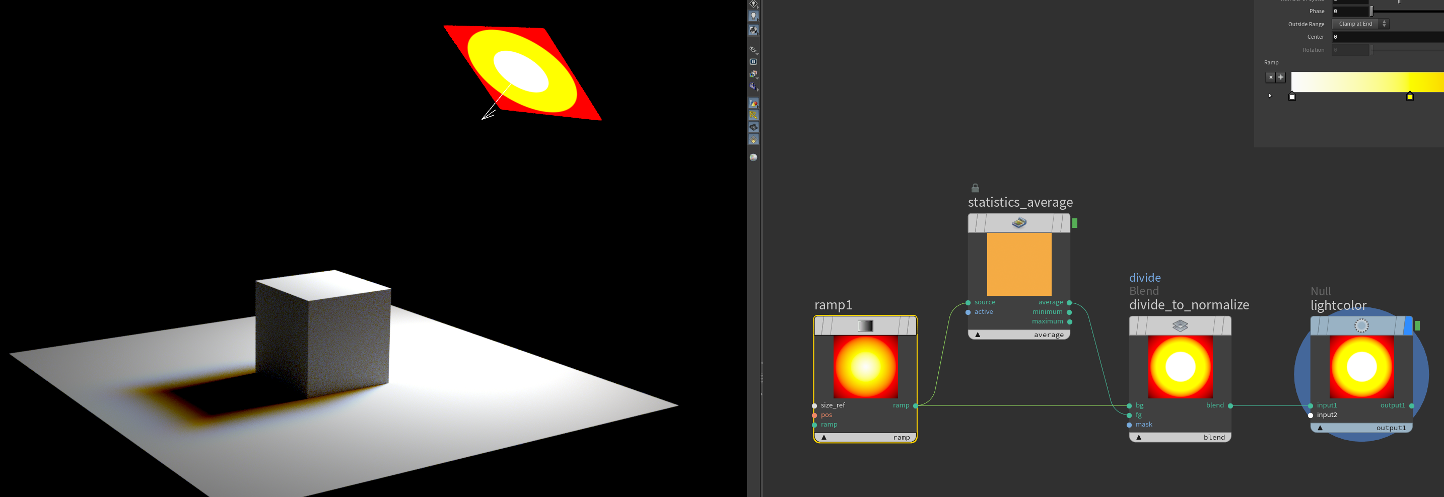
here is a neat little thing: if you make a random ramp and divide it with its average you can use it as a light gel filter and get white light that makes nice penumbras.
Attachments in this post:
http://fx-td.com/houdiniandchill/wp-content/uploads/discord/20254510/01/25/image.png
http://fx-td.com/houdiniandchill/wp-content/uploads/discord/20254510/01/25/houdini_5kZmeogeAZ.mp4
Archived post by mattiasmalmer
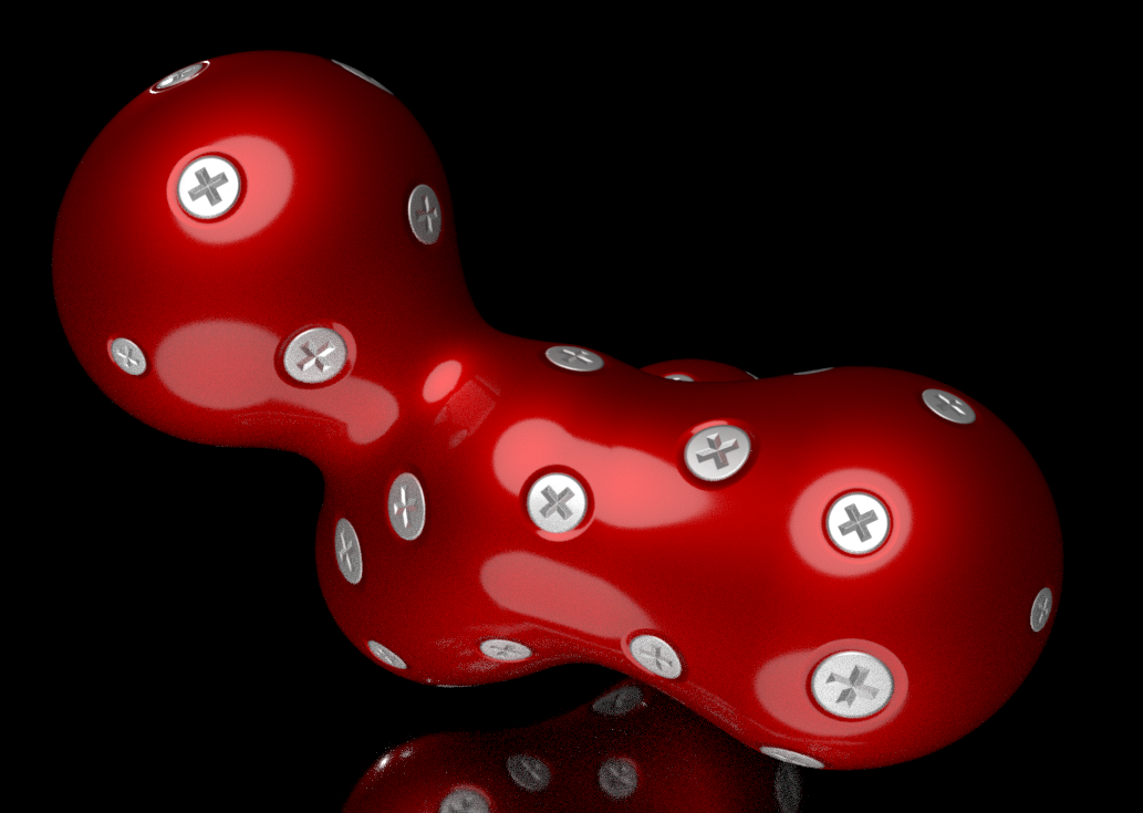
decals with parallaxmap.
here is without. the screw heads gets a little less neat
Decals with Parallaxmaps. Hip file if you want to play around with it.
Attachments in this post:
http://fx-td.com/houdiniandchill/wp-content/uploads/discord/20250109/27/25/image.png
Archived post by mattiasmalmer
it is a bit of a hack to say the least. i grab the normal, tangent and bitangent. make a matrix and transform the raydir into it. use the X and Y coords of that to offset the uvs based on the height in a bitmap. (i do a little loop to incremetally do this but thats just for quality.)
here is the Parallax mapping hipfile. could be fun for decals and such.
Attachments in this post:
http://fx-td.com/houdiniandchill/wp-content/uploads/discord/20251109/25/25/parallax.hiplc
http://fx-td.com/houdiniandchill/wp-content/uploads/discord/20251109/25/25/image.png
Archived post by lwwwwwws
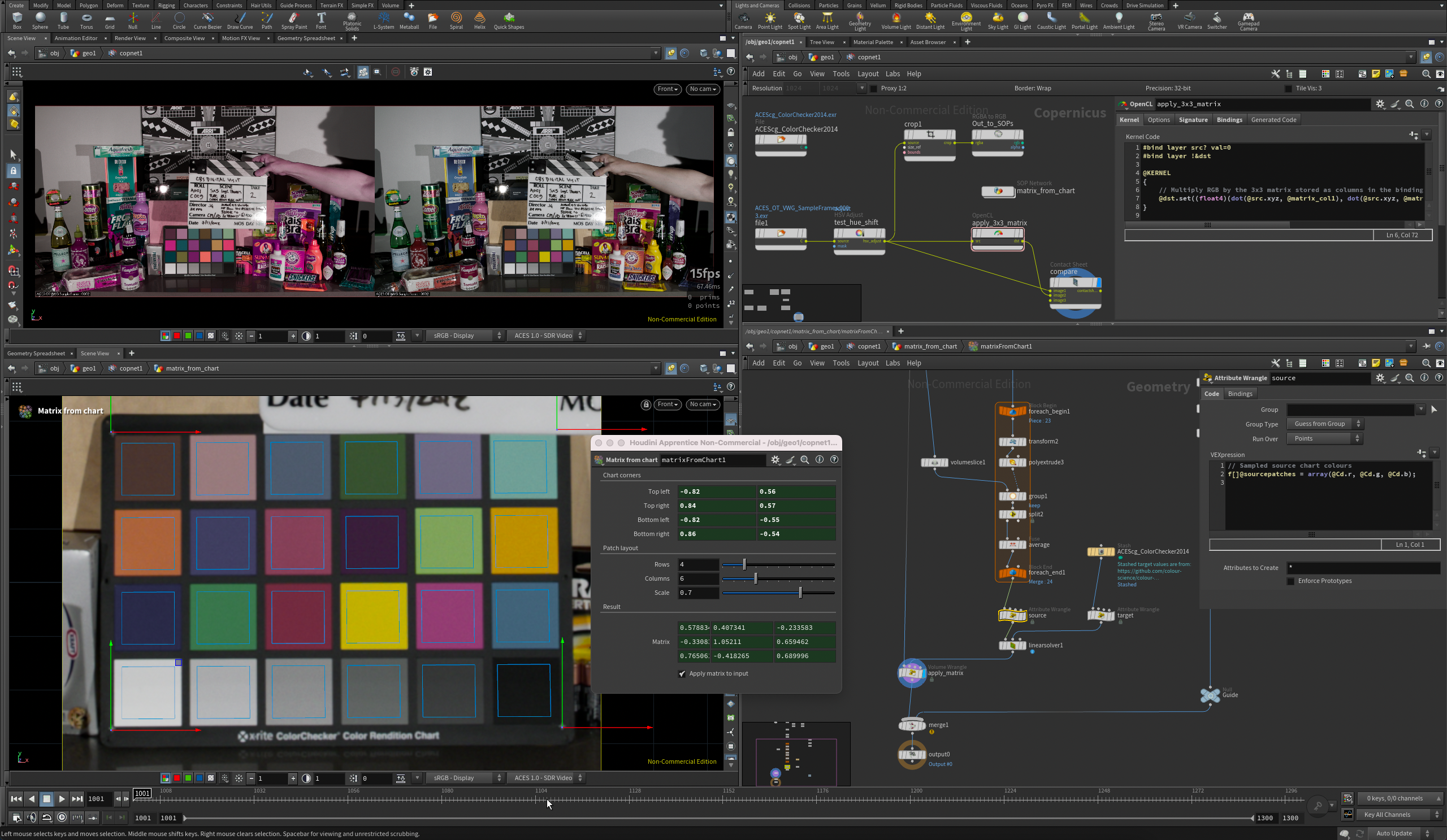
alright here’s something – it uses a similar method to mmColorTarget but is mostly in SOPs, I think it would be quite awkward purely in COPs unless there’s python or expression access to pixel values now in 21.0… it can restore quite busted chart images like the left one back to ACEScg primaries and it’s fast enough to update as you drag the handles around <:tide_pod:415308365942620161> i realise i’ve done this in apprentice which wasn’t very clever of me but maybe an adult could adapt it to be a bit smoother anyway, maybe inside a COPs HDA
Attachments in this post:
http://fx-td.com/houdiniandchill/wp-content/uploads/discord/20254609/23/25/Screenshot_2025-09-23_at_23.21.30.png
http://fx-td.com/houdiniandchill/wp-content/uploads/discord/20254609/23/25/Ls_MatrixFromChart_v01.hipnc
Archived post by igor.elovikov
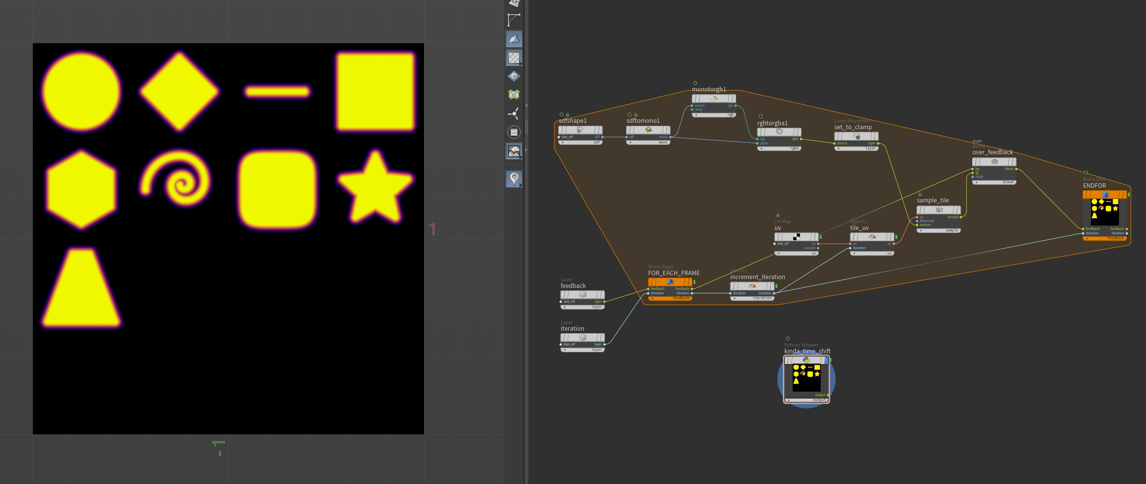
here is the contact sheet packer inside native copernicus context very hacky and very fast though
relies on couple of hacks: * access to time dependent source inside “simulated” block – so packing is basically frame by frame sim * “custom” Time Shift COP based on h21 python snippet
so how is this reliable i’m not sure
here is the hip (i cleaned up it a bit)
i wonder now if i can remove time dependency on time shift (though may be it’s just not possible and I need a stash after that)
hm, the above just leads me to an interesting conclusion
looks like `$F` (`hou.frame()` or `hou,time()`) are evaluated in simulated block context this is basically just one backdoor to inject dependency in block
it’s just one number but can be exploited already for example a packing variations of any op like this example where sdf shape dependent on frame. it’s still cumbersome but randomized contact sheet from *any* operator is quite possible
no, i think i got it wrong, here is what i got from analyzing evaluating path sorry if this is known, but i think it’s quite interesting for block programming
* Compiled block is baking block to apex graph. No expressions, all parameters are evaluated and baked – so no easy iteration and requires this hack of either layer with int or geometry with detail attribute (considering it has a feedback), parametrizing operators is very hard, at least for now, I guess in future sidefx adds additional evaluating context * Simulated block – _all_ expressions are evaluated, this is not an apex execution, it’s a live network. No need for iteration hack – iteration is `$F`. Way easier to parametrize (all expressions are “live”) but getting the result at X iteration is hacky, but easily solveable via Python COP and pulling layer at specific frame
Attachments in this post:
http://fx-td.com/houdiniandchill/wp-content/uploads/discord/20253509/23/25/sheet.gif
http://fx-td.com/houdiniandchill/wp-content/uploads/discord/20253509/23/25/sheet-as-sim.hip
http://fx-td.com/houdiniandchill/wp-content/uploads/discord/20253509/23/25/image.png
http://fx-td.com/houdiniandchill/wp-content/uploads/discord/20253509/23/25/cop-frame-expression.hip
Archived post by toadstorm
okay. i’m gonna eventually make a bloggopost about this but i’ve learned a few things about getting these shitty ass python state handles to work in the correct local space i want
the two main things i found are: * use `cache_previous_parms` to compute *deltas* and then add the delta value to the modified parm in onHandleToState rather than trying to set absolute values for parms in most cases * use `pivot_comp_t[xyz]` and `pivot_comp_r[xyz]` to establish the actual pivot for your handle so that you can properly transform in local space, especially if you are using a control that only exposes specific rotation axes
so as an example in onStateToHandle, where you need to basically set up the handle’s transform based on what’s going on under the hood / in the parameters window:
“`python elif handle == self._handles[“GUIDE_COLUMN”].name(): # set position of handle pivot = self._skeletonCache.point(1).attribValue(“P”) parms[“pivot_comp_tx”] = pivot[0] parms[“pivot_comp_ty”] = pivot[1] parms[“pivot_comp_tz”] = pivot[2] # set rotation prerot = self._skeletonCache.point(2).attribValue(“transform”) prerot_m = hou.Matrix3(prerot) prerot = prerot_m.extractRotates(rotate_order=”xyz”) parms[“xyz_order”] = “xyz” parms[“pivot_comp_rx”] = prerot[0] parms[“pivot_comp_ry”] = prerot[1] parms[“pivot_comp_rz”] = prerot[2] “`
the skeletonCache is a frozen reference to the skeleton geometry that’s being transformed that exists as a member of the state class, that’s so i can have a frame of reference for how the handles need to be oriented. the cache is updated onEndHandleToState
the equivalent code in onHandleToState: “`python elif handle == self._handles[“GUIDE_COLUMN”].name(): # rotate only # self.log(prev_parms) prevrot = hou.Vector3(prev_parms[“rx”], prev_parms[“ry”], prev_parms[“rz”]) rot = hou.Vector3(parms[“rx”], parms[“ry”], parms[“rz”]) delta = rot – prevrot current = node.evalParm(“crane_yaw”) self.log(“rot: {}”.format(rot)) self.log(“prev: {}”.format(prevrot)) # self.log(“delta: {}”.format(delta)) node.parm(“crane_yaw”).set(current + delta[2]) “`
so this way as long as the starting orientation is correct, as long as the user is dragging a handle it’s just computing the difference between prev and current, adding that to the handle, and then basically forgetting about it and resetting the handle’s position and orientation onStateToHandle, the next time the handle is activated
oh and in OnHandleToState i’m making sure that this shit only runs if `ui_event.reason() == hou.uiEventReason.Active`, because the prev_parms dict is always zero when you first activate the handle, which would make my delta calculation all fucked up when the user first grabs the handle (meaning `ui_event.reason()` == `hou.uiEventReason.Start`)
i knew it was going to be a lot of boilerplate but this amount of it feels pretty insane. dunno if there’s an easier way i’m missing but this at least works
Archived post by lwwwwwws
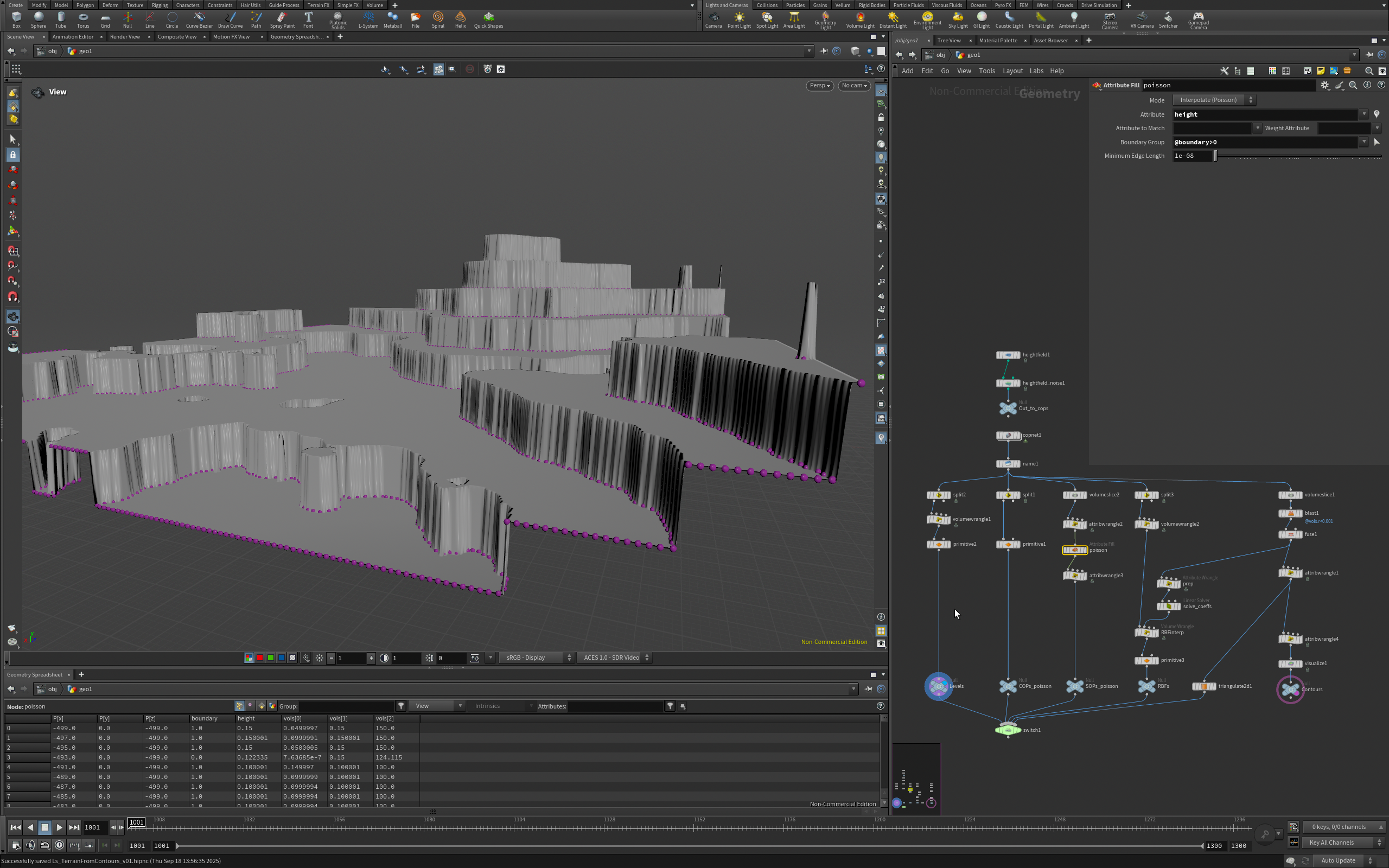
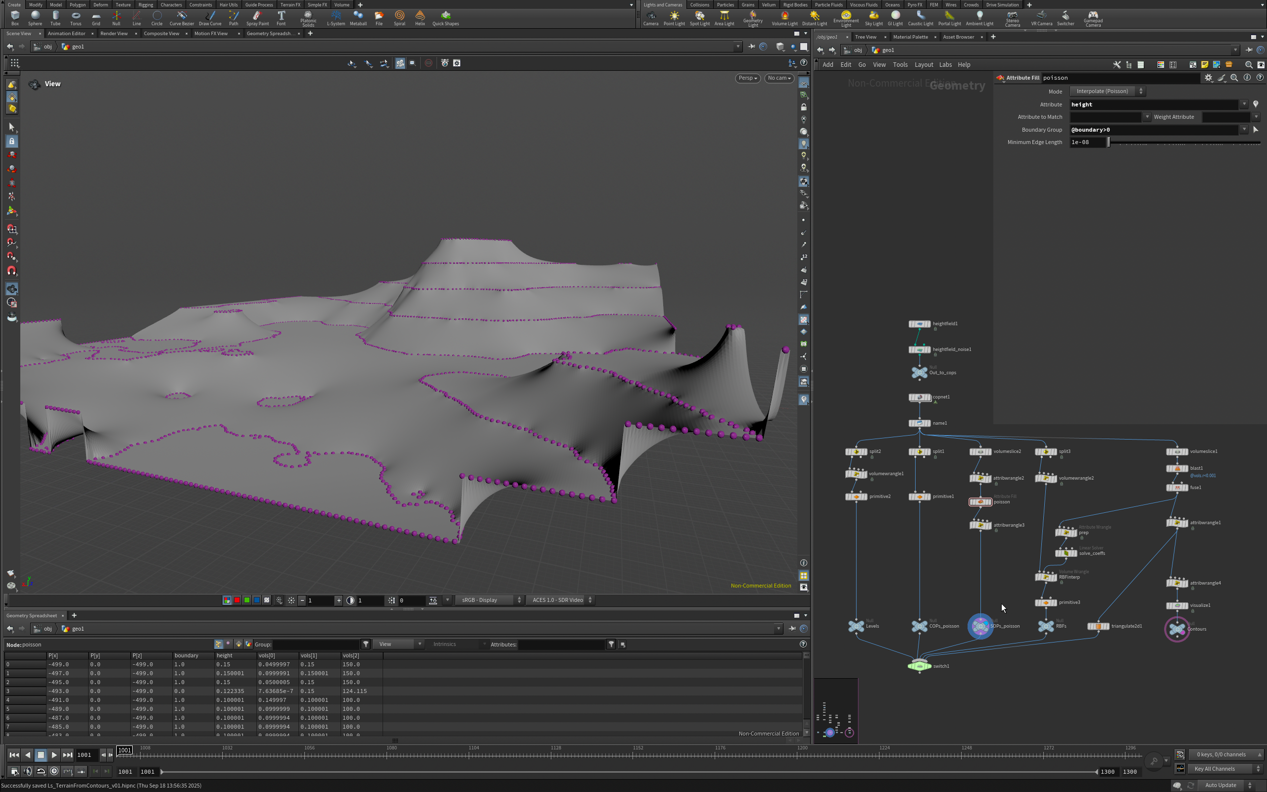
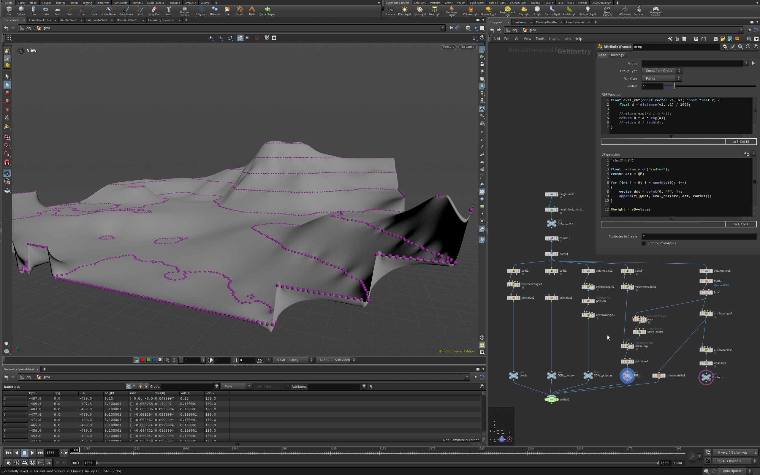
poisson with the smooth fill COP or the attribute fill SOP leave the contour lines pretty visible because they only try to stay C0 smooth… i fear we must reach for everybody’s favourite
the help has an RBF interpolation that i just adapted and keeps things much smoother… good example of how brittle the linear solver can be as well though, changing the RBF function or the numerical range of the inputs can instantly stop it converging or make it output nonsense
Attachments in this post:
http://fx-td.com/houdiniandchill/wp-content/uploads/discord/20253909/18/25/Linear_Solver_SOP.jpeg
http://fx-td.com/houdiniandchill/wp-content/uploads/discord/20253909/18/25/Screenshot_2025-09-18_at_13.57.21.png
http://fx-td.com/houdiniandchill/wp-content/uploads/discord/20253909/18/25/Screenshot_2025-09-18_at_13.57.25.png
http://fx-td.com/houdiniandchill/wp-content/uploads/discord/20253909/18/25/Screenshot_2025-09-18_at_13.57.36.png
http://fx-td.com/houdiniandchill/wp-content/uploads/discord/20253909/18/25/Ls_TerrainFromContours_v01.hipnc
Archived post by beatreichenbach
Hi everyone, I created some themes for Houdini. Of course, just ping me or put in an issue if you see anything that’s wonky or could get improved. Cheers 🙂 github.com/beatreichenbach/houdini-themes
Archived post by jacobs1111
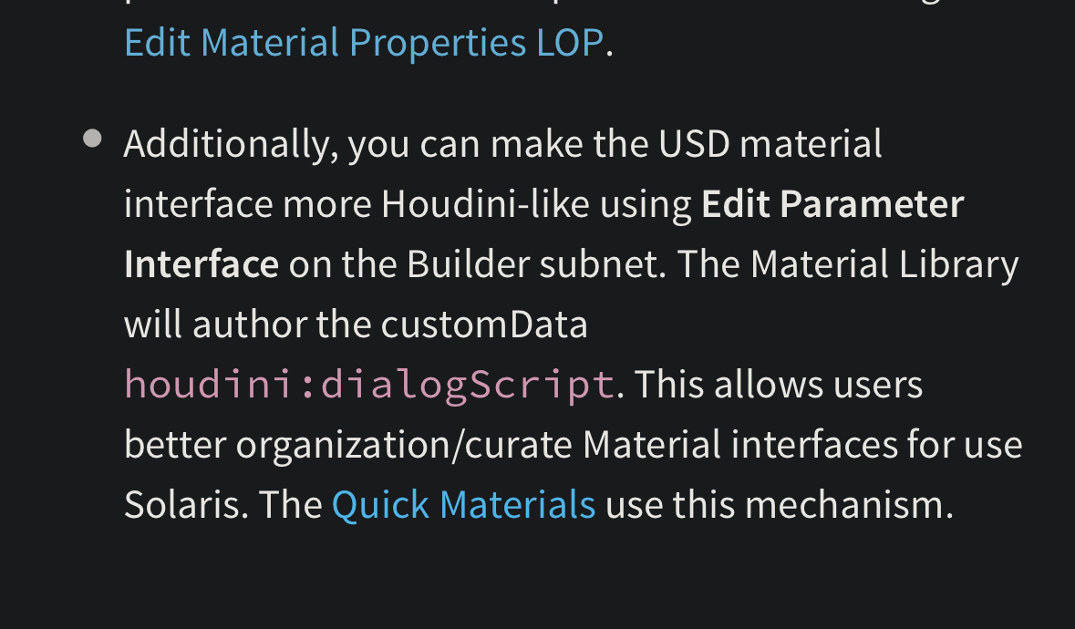
I started looking into this. How to make the edit material parameters user friendly rather than the ugly flat list. Found this in the docs but I got waylaid and didn’t get back to working out how I can get that created for materials already authored without it or a hda material for example
Attachments in this post:
http://fx-td.com/houdiniandchill/wp-content/uploads/discord/20251809/15/25/IMG_7793.png